A Chromatic Button MIDI Keyboard
This is a project I've wanted to build since about 2013, and I finally got around to finishing it in 2020.
It's a velocity sensitive MIDI controller with the same layout as a chromatic button accordion.
Background
I'm not much of a musician, but I occasionally like to nerd out about music theory. So when I saw the Chromatic Button Accordion (CBA) with it's regular hexagonal array of keys I was curious. After reading more, I was hooked on the idea of an instrument where every musical interval and chord shape mapped to the same physical intervals and shapes on the keyboard, no matter their root note. Every major scale can be played the same way, just by changing the starting note.
I went so far as to buy a Roland FR-1b to play with and practice scales. It was nice, because I could plug in headphones and noodle around silently. I could even disable the bellows and control other MIDI synthesizers with it, as if it were an alternative keyboard layout.
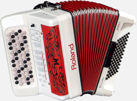
After a year or two, I sold it to the wonderful Lucas Hicks (one of my favorite square dance callers), because he could actually play the CBA well and was interested in practicing silently.
But I never stopped wanting a small-form factor velocity sensitive MIDI controller with that layout and no bellows.
Unfortunately, the only CBA MIDI controllers on the market are large and upwards of $2,000. But I figured I could build my own to play with.
The design ideas
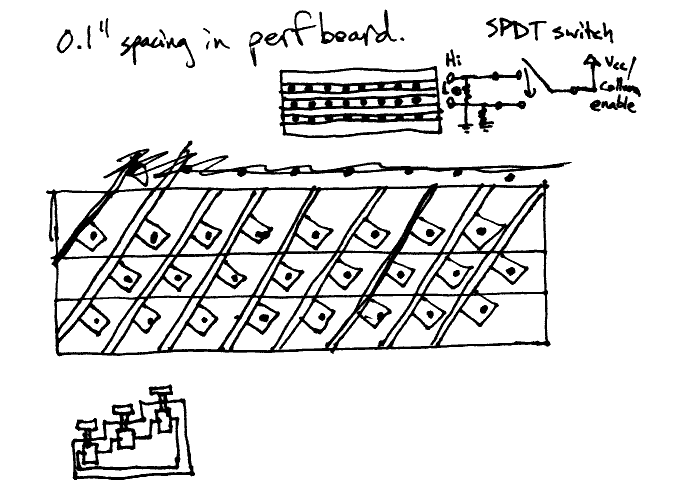
In 2013 I came up with plans for the firmware and for building it on 0.1" protoboard with SPDT switches that would fit and bought parts. Five right angle switches (like these) would be pointing up on boards perpendicular to a carrier board, the switch boards slanted at a 60 degree angle so that when arranged across the board they would form a hexagonal grid of buttons. With this arrangement, each row of switches could easily be at a different height, like on a real CBA.
Here's a design sketch from 2013, showing three rows instead of five:
Now that I can layout my own printed circuit boards, I simplified the design a bit. There is now a single board per octave, and the switches (this model) are mounted flat to the board, projecting up. This means that all switches are at the same height, but that is fine for this project. The perpendicular board design could still be done with custom PCBs, but I wanted to prototype with this easier to assemble design first.
The reason for using SPDT (single-pole, dual-throw) switches is "velocity sensing". With two contacts (the "throws"), it's possible to measure how quickly the switch is being pressed. At rest, the switch is held up by a spring and the single pole is making contact with the upper contact. When pressed, the upper connection is broken, and some time later the pole makes contact the the lower contact. By measuring that time, you can infer the speed of the switch.
The switches are read with parallel-in serial-out shift registers in a daisy chain. This simplifies the firmware, since you don't need key matrix code, and allows you to chain together as many octave boards as you'd like.
The most difficult design problem was mechanical: what to use for the key caps. Real CBAs have wide circular buttons, sometimes with white and black keys, sometimes all one color. I wanted white and black keys of about the same size as a real CBA. The only off-the-shelf key caps that would snap onto the switches came in different colors, including white and black, but were about the size of an accordion's bass buttons. Too small.
In addition, the switch posts were square. I had a real "square peg in a round hole" problem when it came to designing my own key caps. A 3D printed part wouldn't have enough resolution to grab the small features of the post, and I dislike the feel and look of 3D printed parts anyway. Hardware stores have wooden round hole plugs that would work very nicely and could be dyed or painted different colors, but I'd have to drill centered holes in each one. That's doable with a a drill press and a jig, but didn't sound particularly fun when each octave has 20 keys (5 rows of 4 keys) and I wanted at least three octaves. And I'd still have a square peg and round hole that I'd need to fill with epoxy to attach the two.
Last fall I had the epiphany that I could just make the keys themselves out of epoxy resin. If I had a mold for all the keys, I could simply dip them in a two-part plastic resin and let them harden over the square posts and snap features. That's what I've done with this project.
Hardware
The schematic, per se, doesn't exist. It was written in the Skidl language by Dave Vandenbout, which I learned of from his talk at the 2019 KiCon conference. Skidl is a neat and fun to use Python library for creating circuit netlists that can be imported by KiCad. It replaces Eeschema in the KiCad workflow with a textual representation of your circuit, which you can then layout with PcbNew.
Where the tool really shines is repetitive circuits, because you can define a common block once and then instantiate it multiple times in a loop, which is a good fit for this project1.
Originally, I planned on doing the entire keyboard as one circuit board, but thought better of it and settled on a placing a single octave on a PCB than can be copied and daisy chained. That made using Skidl a little less useful for this project, since each octave board only has 20 switches, but I still liked using it.
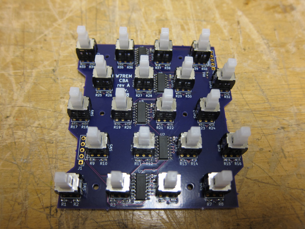
The PCB is as simple as can be: five shift registers in a daisy chain, each reading the dual contacts from four switches. This is a five row CBA, though it would be easy to implement three or six rows. The neat thing about having four columns of switches is that each board is a single octave, and each shift register is fully utilized.
The layout was done manually with PcbNew. The array layout features weren't fully implemented at the time, and it would have been nice to have a tool like Skidl for setting the coordinates of components. Perhaps that would be a nice addition to Skidl itself. I was able to work around that frustration by setting up a rectangular grid with different x and y dimensions that included points on the hexagonal grid I really wanted. Then it was easy to snap the components onto the grid.
Here's the final board, ready for keycaps and daisy chain connectors:
And here's the Nucleo dev board which reads the keys and sends MIDI output:
Software
The microcontroller board is an STM NUCLEO_L476RG that I happened to have on hand, running the Mbed OS 5.
I turned the RTOS features off and I configured my own interrupt ISR
to sample the keys because there was a lot of jitter in the
us_ticker API.
On each sample the shift registers are latched and then read with a single SPI command into an array of bits. Keys are sampled every 100us (10kHz), and the SPI clock runs at 10MHz.
A simple state machine tracks the state and timing of each key. When a key is pressed down to the second contact, a MIDI note on message is generated with the right velocity, and when it is released and returned to its resting position a MIDI note off message is generated. This was a fun bit of code to write, with some neat bit twiddling to do.
The regular key layout structure made it easy to map keys to MIDI notes, and the whole keyboard can be easily configured for any number of octaves and transposed to any desired musical key. The mapping between the actual switching time to MIDI velocity codes is configurable and adjusted until it feels right.
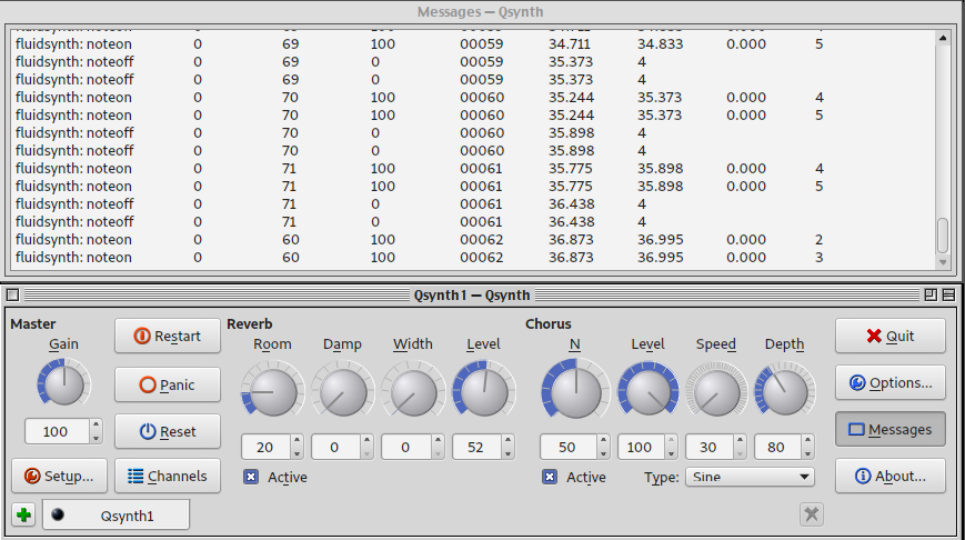
I used Qsynth for testing the MIDI output, and it conveniently shows the note on and off events for easy debugging:
Mechanical
This was the really fun part.
Mold form
I made the mold form with foam core board and hex bolts to define the shape of the keys. ("Made with real hexagons. Accept no substitutes!")
I used the PCB as a template for locating and marking holes in the foam core, and then cut square holes with a hobby knife. Then I could firmly screw in all the bolts.
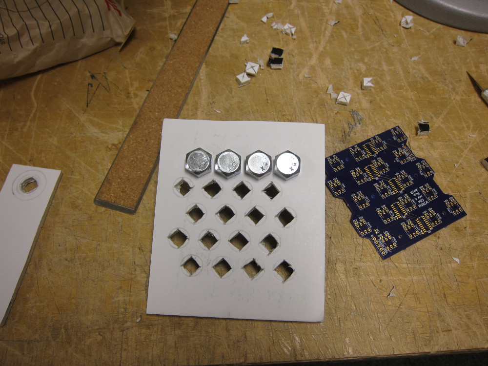
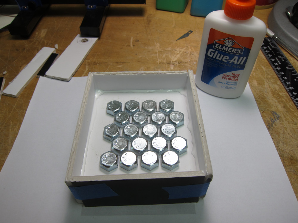
The finished mold form, waiting to dry:
Mold making attempt 1
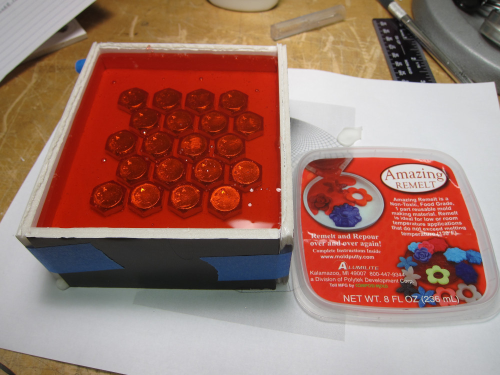
The first material I selected for the mold was Alumilite's Amazing Remelt. This was very easy to work with. Here is the pour after melting in a toaster oven:
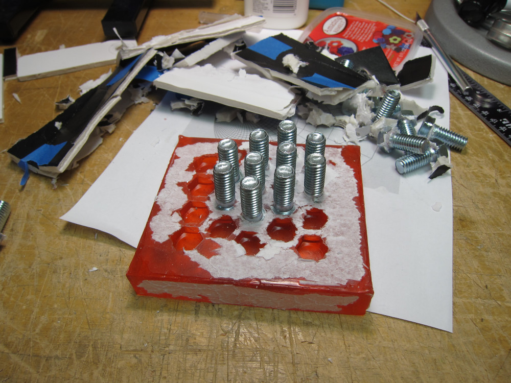
I forgot to apply a mold release (spray or petroleum jelly), and the mold form was destroyed when taking the mold out. Bits of paper were stuck to the mold as well. I was surprised that it was easy to scrape all that off, especially when I got the mold damp with water.
It was also easy to weld and repair with a hot pick when I accidentally tore part of the mold:
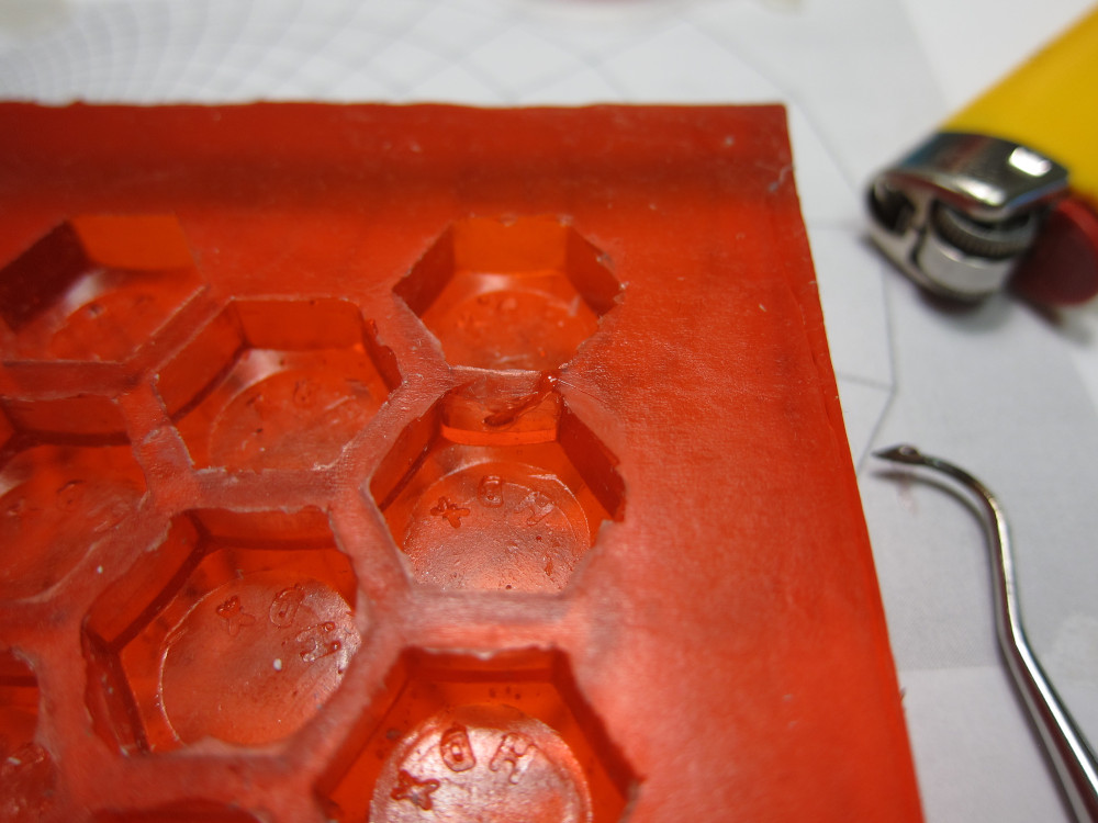
Unfortunately, when I tried to cast resin it developed a lot of bubbles which made the surface of the cast parts very rough. Not acceptable.
Mold making attempt 2
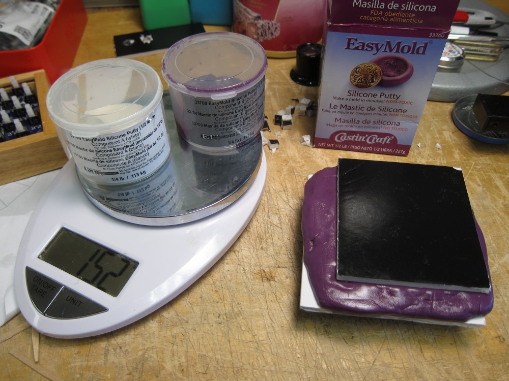
The next mold material I tried worked beautifully. It's EasyMold by Castin' Craft, a silicone rubber mold made from a two part putty. You mix the two parts together, and then press it into the mold form.
I had to build a new mold frame, but this time I didn't need walls to contain the putty and I used the drill press and a step bit instead of cutting holes with a knife.
I didn't fill all the gaps between the bolts on the first attempt, which left some extra flashing on each key cap. Luckily the material sticks to itself, so filling those portions was a simple matter of filling the holes with more putty and reinserting some bolts. (The black marks in this photo indicates the black keys.)
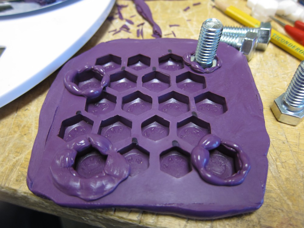
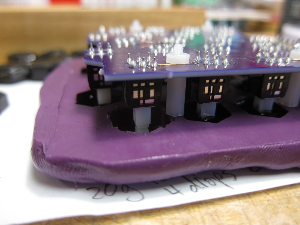
For registration during pours, I pushed wires into the finished mold so that they could hold the PCB in place by fitting into some standoffs on the PCB. This worked pretty well.
Pouring the keys
I used Alumilite's two part resin for casting. Before mixing the two parts, I added some dye (either white or black) to the B part. Then I mixed and poured the resin into the pre-heated mold. Pre-heating helps small parts like this fully cure and hardened.
Molding the black and white keys is a two part process. The black keys are poured and hardened first. Then the white resin is poured and the black keys are stuffed back into the mold, ensuring perfect registration between the two colors. The black keys are done first because there are fewer of them and it's easier to get them back into the mold for the second pour.
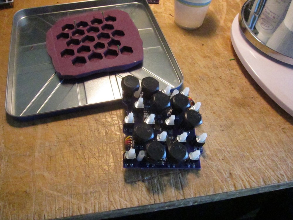
Here's a picture of the black key pour, which also highlights the standoff used to set the switch depth and registration (the registration wire is inside the standoff):
And the result:
Here's an almost finished octave board. In the bottom row there's a little cleanup to do after some white resin spilled into a black key cup. Luckily, it peeled off very easily.
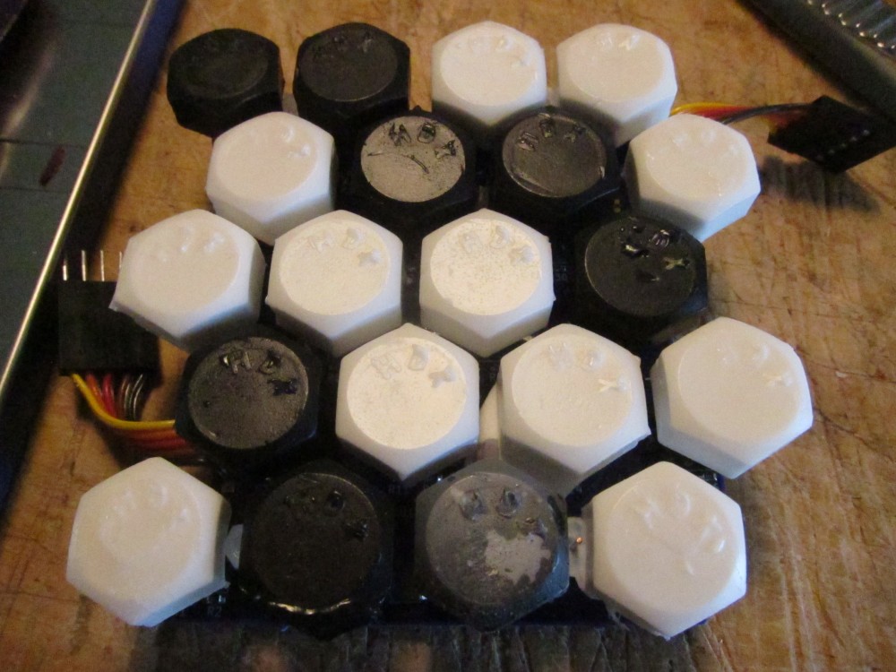
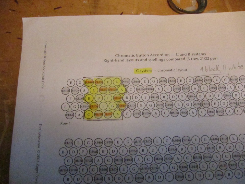
This is a good time to point out that I goofed and poured one of the black keys as a white key for each octave I did. The rightmost key on the second row from the bottom (B flat) should be black.
Here's the CBA layout chart I was working from:
Bodge wires
The black key pour photo also shows a bodge wire to fix a PCB goof where I routed some traces too close to the standoff mounting hole. That wouldn't have been a problem, except the standoffs are M2.5 and I accidentally used footprints for M2.2 standoffs in KiCad. Oops. After drilling out the holes to the right size, I had to reconnect the broken traces.
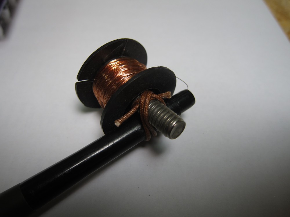
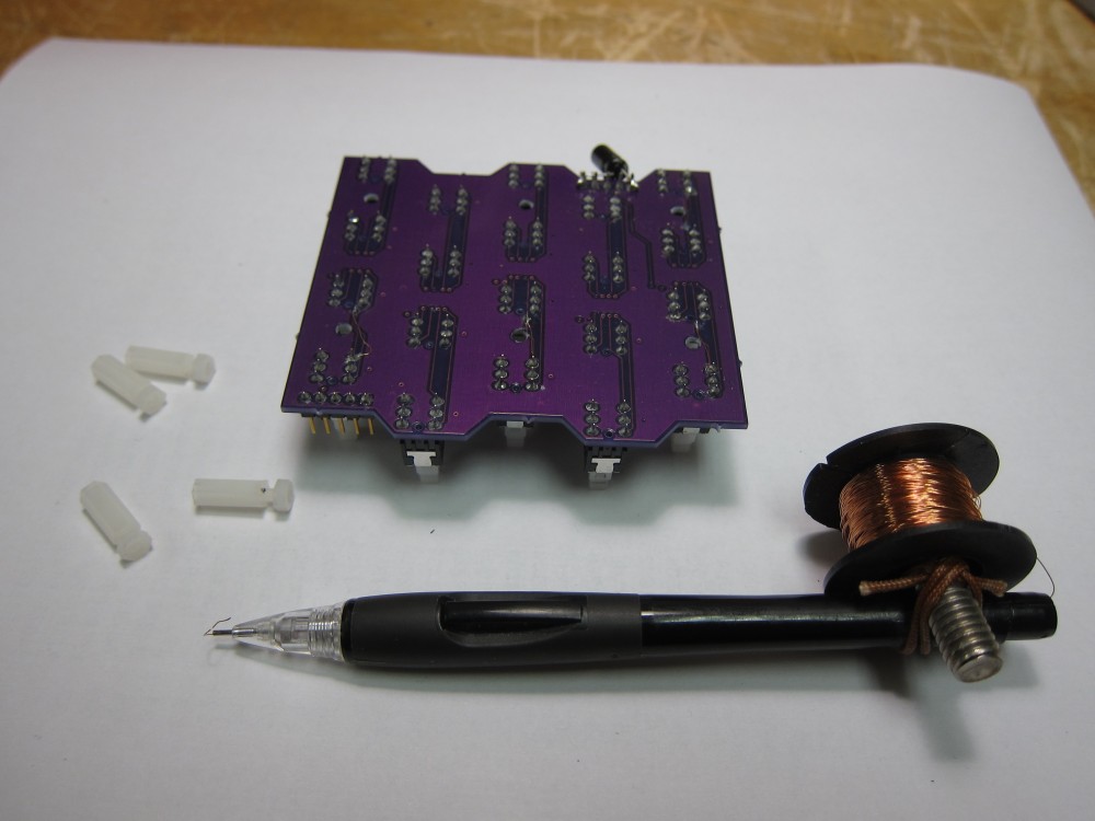
I used my wiring pen for this fix2:
Connecting it all up
Here's how the boards are daisy chained with Dupont connectors:
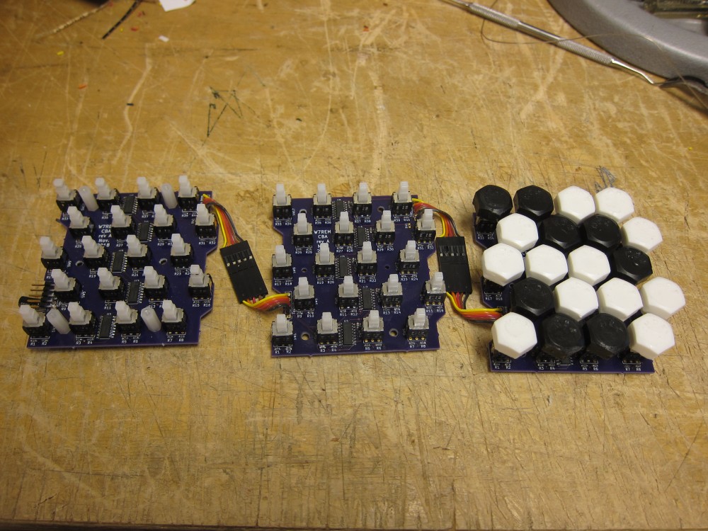
It's a bit of an EMI monster in this configuration, and it creates noticeable static on a nearby FM receiver. I'll have to fix that in Rev B.
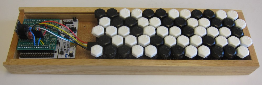
I don't know why I was so lucky, but just as I got all these boards connected and was thinking about woodworking a wooden box to house them, my dad sent me a kitchen knife in a wooden box that fit three octave boards and my Nucleo board almost perfectly. It's the right depth and the perfect width, with only a millimeter clearance.
Here's the fully assembled keyboard:
Playing it
I'm happy to report that this thing works pretty well! It's not flawless, but it is fun.
The two main problems with this prototype:
- Sometimes key down and key up events aren't detected, so a note won't sound or will sound "forever".
- The switch posts will sometimes bind and not travel smoothly, especially when a key is pressed off center.
The first problem might be software (likely the state machine logic), but the second problem will require redesigning the PCB with new switches. For now, it is good enough to scratch my itch.
Footnotes:
The entire Skidl code is only 116 lines. Here's a sample:
# Build a button group for a single shift register.  The shift out net
# is passed in as sdo, and the shift in pin is returned.  Successive
# calls will build the shift register chain out away from the SPI
# connector.
@subcircuit
def button_group(sdo):
  shift_reg = shift_reg_template.copy()
  decouple = decouple_template.copy()

  shift_reg.VCC += vin, decouple[1]
  shift_reg.GND += gnd, decouple[2]

  # SPI
  shift_reg['~PL'] += spi_cs # Parallel latch is chip select.
  shift_reg.CP += spi_sclk
  shift_reg.Q7 += sdo

  shift_reg['~CE'] += gnd # Always enabled.
  shift_reg['~Q7'] += NC # Not needed.

  # MSB is shifted out first.  Bit pairs are (NC, NO) contacts.
  make_button(shift_reg.D7, shift_reg.D6)
  make_button(shift_reg.D5, shift_reg.D4)
  make_button(shift_reg.D3, shift_reg.D2)
  make_button(shift_reg.D1, shift_reg.D0)

  # Shift in pin
  return shift_reg.DS

# Create an octave of keys
@subcircuit
def octave(sdo):
  num_rows = 5
  chain = sdo
  while num_rows > 0:
    chain = button_group(chain)
    num_rows -= 1
  return chain
I built my wiring pen with a mechanical pencil, a carriage bolt, some Handy Hundred cord, a double constrictor knot (one of my favorites), and some CA glue. I carved a notch in the pencil body to help hold the bolt in place before tying and securing the knot with the glue. The spool holds a low temp enamel coated copper wire (34 AWG P155). The bolt can be turned to adjust spool tension. The tricky part is fishing the wire through the tip. For that I fold a length of the wire in half, run it through the tip backwards, hook the spool wire and then pull it back down.